Task 27-10-10-01 - Control Rod Inspections
1. Elevator Control Rod Inspection
- A. Remove the tunnel covers, ref AMM Task 25-70-01-01.
- B. Remove the elevator horn inspection panels.
- C. Inspect the rods for cracks, gouges or scratches.
- D. Inspect the connecting hardware.
- (1) Ensure the front rod end has safety wire and the safety wire is retained within the fastener stackup.
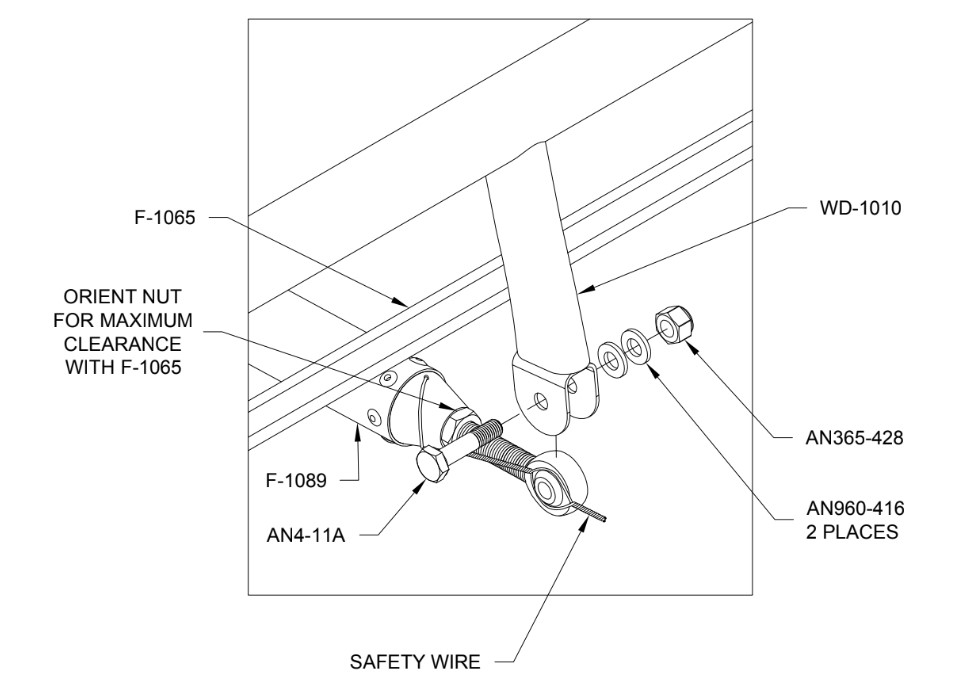
- (2) Check the jam nuts for condition and security.
- (3) Check the torque stripe for continuity. If broken, re-tighten jam nuts and re-apply torque stripe. Ensure more rod end engagement is over half.
- (4) Check the torque on the AN365-428 nut on the WD-1010 assembly.

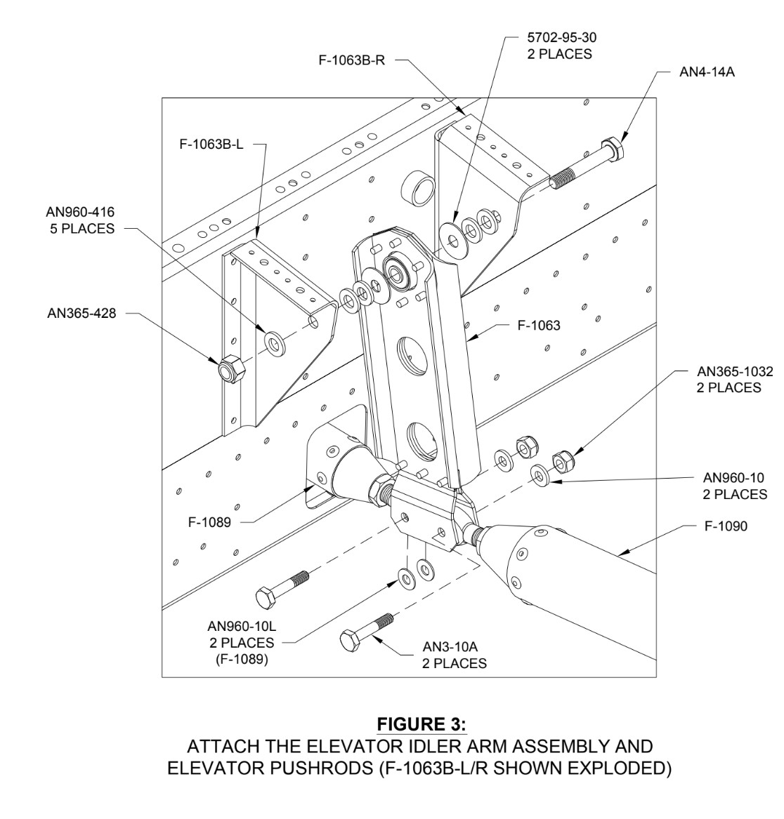
- (5) Check the torque on the AN365-1032 nuts on the Elevator Idler Arm.
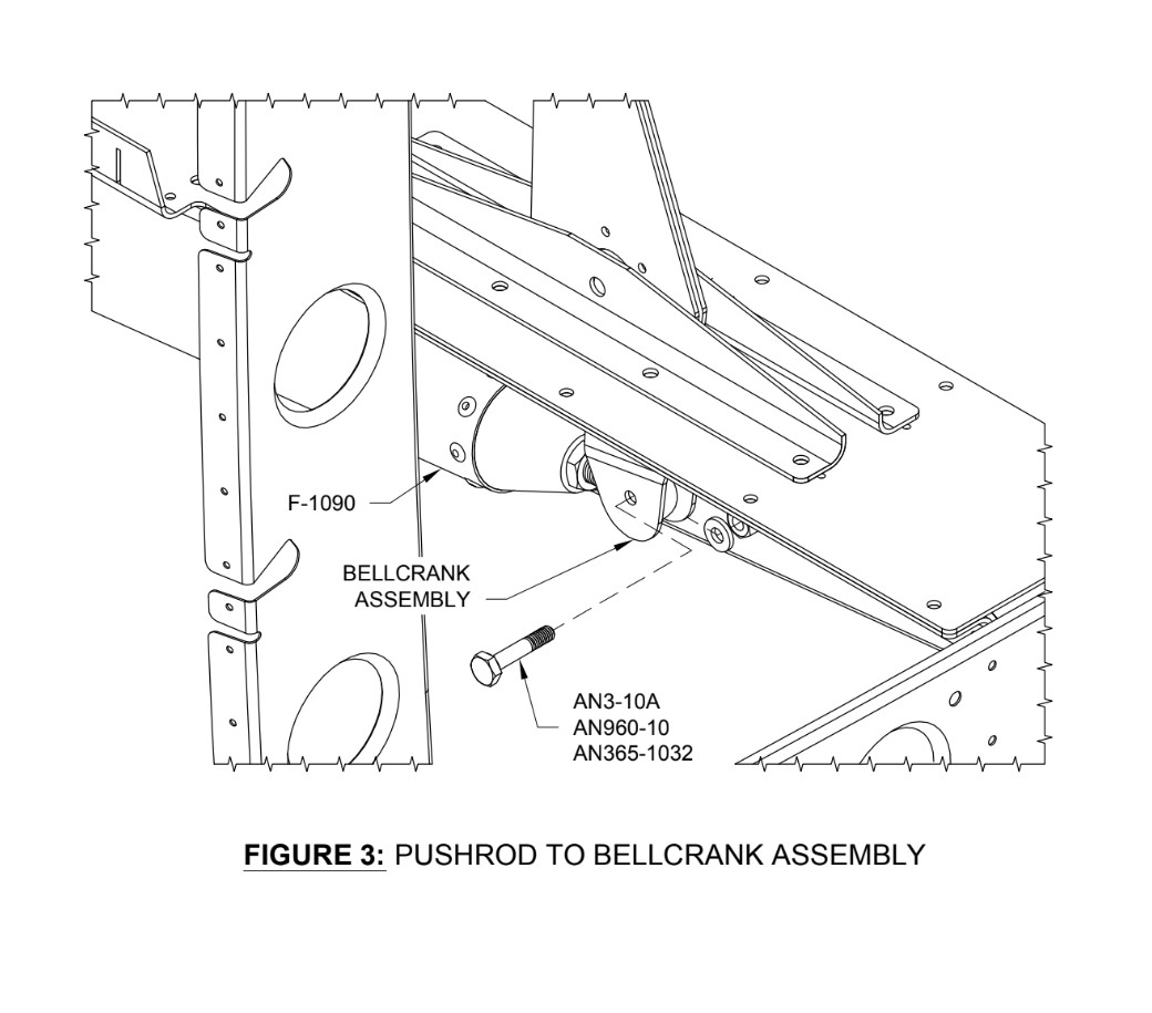
- (6) Check the torque on the AN365-1032 nuts on the Elevator Bellcrank Assy.
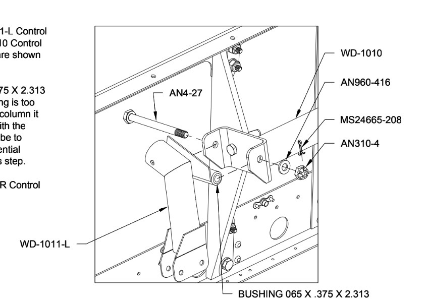
- (7) Inspect the attaching hardware on the elevator horn for proper torque and security.
- (1) Ensure the front rod end has safety wire and the safety wire is retained within the fastener stackup.
2. Stick Base Inspections
- A. Remove the front seats, ref AMM Task 25-10-01-01 .
- B. Remove the access panel in between the seat rails.
- C. Inspect the attaching fasteners for security.
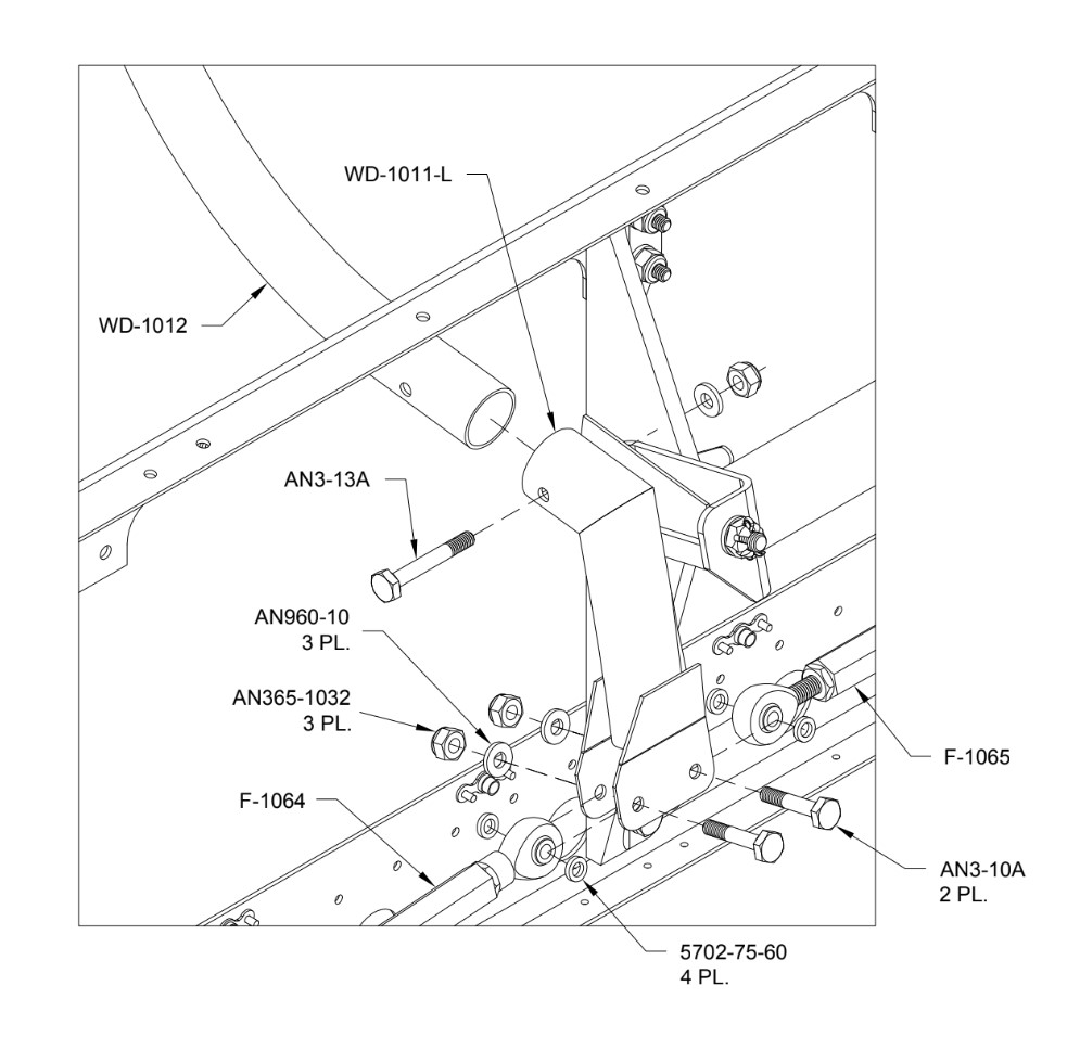
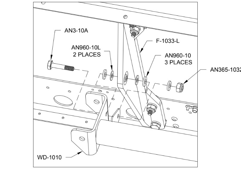
3. Aileron Control Rod Inspections
- A. Remove the wing root fairings as required.
- B. Inspect the aileron pushrod attachment for security.
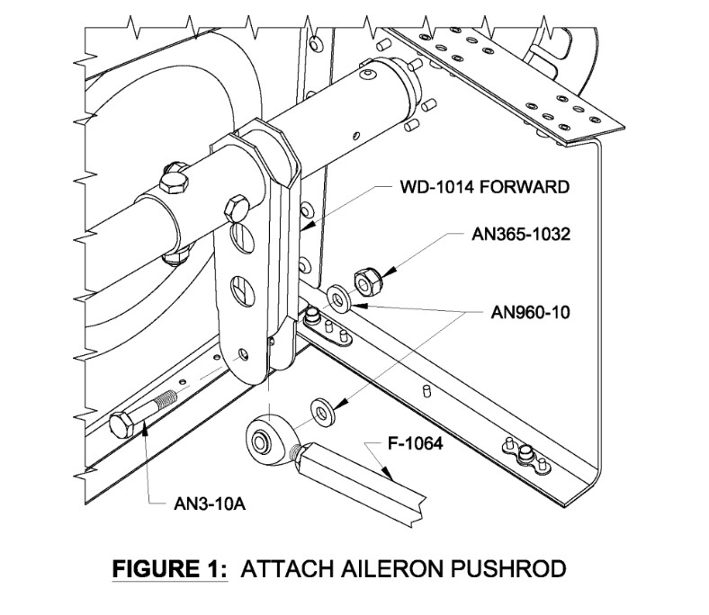
- C. Inspect the Wing aileron control rod attachment for security.
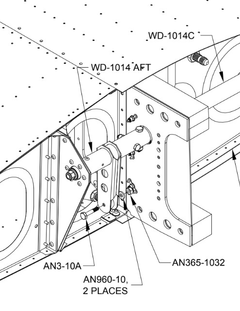
4. Aileron Bellcrank Inspection
- A. Remove the outboard wing access panel.
- B. Inspect the aileron bellcrank pushrod attachments for security.
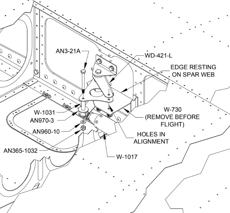
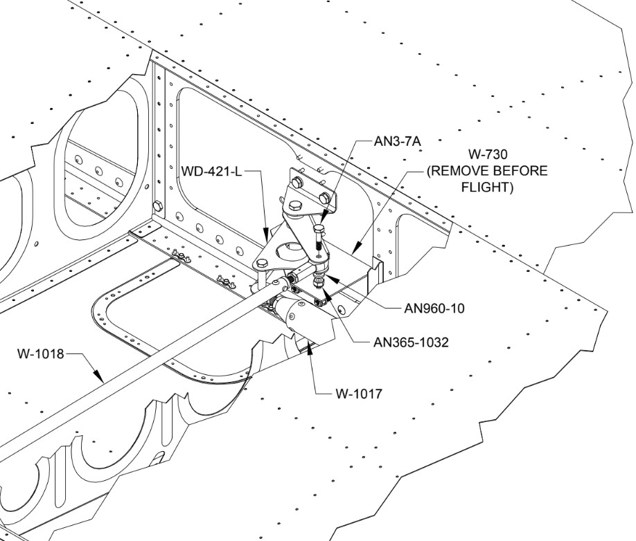
- C. On the right wing, inspect the autopilot servo connection and attachment fittings.
5. Rudder Cable Inspection
- A. Remove the forward tunnel covers if required, ref AMM Task 25-70-01-01
- B. Ensure the castle nut is correctly torqued and the MS24655-132 cotter pin is present on the rudder control arms.